Turning Online Calculators: Shop-Safe Setup Checks
Use turning online calculators as setup-check tools: if the suggested RPM or horsepower is close to your machine limit, I back off somewhat and check stickout, toolholder rigidity, and material before cutting. Skip that check and you invite chatter, broken inserts, tripped drives, or a cut that stalls under load. This guide shows how I read those calculators against real setup conditions.
What a turning calculator is for


A turning calculator is a setup aid, not a process plan you can follow blind. It turns material, diameter, feed, and depth of cut into spindle speed, feed rate, material removal rate, cutting power, and torque, so a machinist can see whether the cut fits the machine and the part.
I use it early in planning. Enter the material preset, insert data, diameter range, max RPM, and machine power, then compare the output to the actual lathe, chuck, overhang, and part stiffness.
Formula helper versus setup-check tool
Competitors often stop at the formula. That misses the useful part. The calculator should tell you whether a cut makes sense on a specific lathe, with a specific holder, insert geometry, and stickout.
It also catches bad assumptions fast. A power estimate can look fine on screen while the setup is still risky because the bar is long, the wall is thin, or the insert nose radius does not suit the finish pass.
Where the calculator fits in the job plan
I use it before the first part, again after the roughing pass is chosen, and once more when finishing diameter changes spindle speed. Treat the output as something to check against machine limits, not permission to cut.
What it cannot tell you
A calculator cannot see interrupted cuts, worn inserts, poor chip evacuation, loose turret clamping, or a part that chatters only at one diameter. It also cannot fix bad tool geometry. A sharp feed rate on paper can still fail if the insert shape does not suit the cut.
📊 Hard turning is performed above 45 Rockwell C. Source: Turning.
Which inputs matter most before you calculate
The most important inputs are material, insert grade, diameter range, depth of cut, feed per revolution, max RPM, machine power, and rigidity. Those values move the output more than small tweaks to cycle-time math.
Material and tool preset selection
Pick the preset that matches the workpiece and tool material first. Aluminum, steel, stainless, titanium, and cast iron cut differently because their cutting speeds, chip control, and cutting forces differ. The calculator also supports 30+ materials and multiple unit systems.
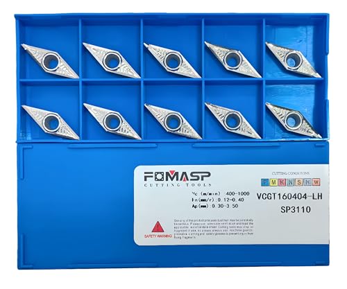
Use the insert grade and geometry that match the operation. A finishing insert with a small nose radius is not the same choice as a roughing insert on a long overhang. If the geometry is wrong, the numbers mean less.
Starting and finished diameter
Diameter matters because RPM changes as diameter changes. OD turning starts at the larger diameter and usually needs higher RPM as the tool moves toward a smaller finished size. One part may need two very different spindle settings.
Max RPM, power, and rigidity limits
Do not ignore the machine ceiling. Check chuck speed limits, spindle max RPM, drive load, and whether the bar or tube is long enough to flex. A calculator can show a safe-looking spindle speed while the setup still vibrates.
| Setup input | Example value | Shop decision |
|---|---|---|
| Material | 4140 steel | Use a steel preset, then verify chip control and power |
| Tool / insert | General-purpose carbide rougher | Check nose radius, rake, and holder rigidity |
| OD starting diameter | 2.000 in | Set roughing RPM from the larger diameter |
| OD finishing diameter | 1.500 in | Expect higher RPM if using constant surface speed |
| Depth of cut | 0.080 in roughing | Check horsepower and chatter before the first pass |
| Max RPM | 2,500 | Confirm the calc result stays below this at all diameters |
| Machine power | 7.5 hp usable | Compare against calculator horsepower with margin |

How do you calculate spindle speed for turning?
Spindle speed comes from cutting speed and workpiece diameter. The calculator converts surface speed into RPM, so a larger diameter needs a lower spindle speed than a smaller diameter at the same cutting speed. Constant surface speed adjusts RPM as the tool moves; fixed RPM does not.
Surface speed to RPM
Turning calculators often use cutting speed in m/min or surface speed in SFM, then convert that to spindle speed. That is why the same tool setting cannot be copied across all diameters without adjustment.
Why diameter changes RPM
On a larger diameter, one revolution covers more surface, so the spindle must turn slower to keep the same surface speed. As the tool moves inward on an OD cut, the spindle speed rises unless the machine is held at fixed RPM.
Fixed RPM versus constant surface speed
Fixed RPM is simple and stable, which helps on roughing passes, interrupted cuts, and shaky setups. Constant surface speed works better when diameter changes a lot, especially on finishing cuts, because it keeps cutting speed more even across the profile.
How do you calculate feed rate in lathe turning?
Feed rate in turning comes from feed per revolution multiplied by spindle speed. The calculator can show feed in inches per minute or mm/min, which helps compare finish quality, chip load, and cycle time on a real lathe.
Feed per rev and linear feed speed
Feed per rev sets how much the tool advances each spindle revolution. Linear feed speed rises when RPM rises, so a constant feed per rev does not mean a constant feed speed at the carriage.
Roughing versus finishing feed
Roughing usually needs a heavier feed to keep the tool cutting cleanly and moving chips. Finishing usually uses a lighter feed to control surface finish and size. A calculator can suggest numbers, but the insert geometry and machine stiffness still decide whether the pass feels stable.
What feed does to finish and tool load
Higher feed increases chip thickness, cutting load, and often chatter risk. Lower feed can improve finish, but if it gets too light, the insert may rub instead of cut. That is common on small-diameter work and on thin-wall parts.
How do you estimate material removal rate and cutting power?
Material removal rate comes from depth of cut, feed, and cutting speed. Cutting power is then estimated from the removal load and the material’s specific cutting force kc. The output only helps if you compare it to the lathe’s usable horsepower or kilowatt capacity.
MRR from DOC, feed, and speed
MRR shows how much volume is removed per minute. It is a productivity number, but it also hints at heat and force. A big MRR can look efficient while quietly exceeding the machine or the setup.
Specific cutting force and horsepower
Specific cutting force kc is the bridge between chip load and power. Steel generally needs more force than aluminum, and stainless or titanium can climb higher still. That is why two cuts with the same MRR can load the spindle very differently.
Pass/fail against machine capacity
Use a simple pass/fail check: if calculated horsepower is close to machine output, if torque is near the drive limit, or if the part is thin or long, reduce the cut. Back off before the machine is forced to prove the spreadsheet wrong.
| Operation | Example pass signal | Example fail signal |
|---|---|---|
| OD turning | Power below machine limit with margin | RPM near max and chatter at the first roughing pass |
| Boring | Short bar, rigid boring bar, stable chip break | Long overhang, squeal, or a bouncing finish |
| Facing | Even chip across the face and stable spindle load | Center slowdown, rubbing, or interrupted contact marks |
| Threading | Manual confirmation of pitch, infeed, and relief | Calculator used alone without thread-specific checks |
Can a turning calculator work for boring, facing, and threading too?
Yes, but each operation needs its own separate check. A calculator can support boring and facing because both are turning-type cuts, and it can help with threading setup math, but threading needs extra manual checks for pitch, entry, relief, and synchronization.
OD turning
OD turning is the cleanest match for the calculator because the tool cuts the outside diameter and the diameter change is easy to track. This is where surface speed, RPM, feed, and MRR line up most predictably.
Internal boring
Boring cuts the inside surface of a hole or tube. The calculator still helps with speed and feed, but the setup is more vibration-prone because the bar is usually longer and less stiff. Thin-wall work makes that worse.
Facing cuts
Facing removes material from the end of a workpiece. Diameter changes every second of the cut, so the calculator’s RPM chart matters more here than in a straight OD pass. Watch the center closely; rubbing can start there.
Threading limits and manual checks
Threading is a special case. The calculator can help with spindle speed and basic load estimates, but pitch, tool profile, synchronization, and lead-in geometry still need manual confirmation. A plain RPM result is not enough.
Setup checklist: how to read calculator output before you cut
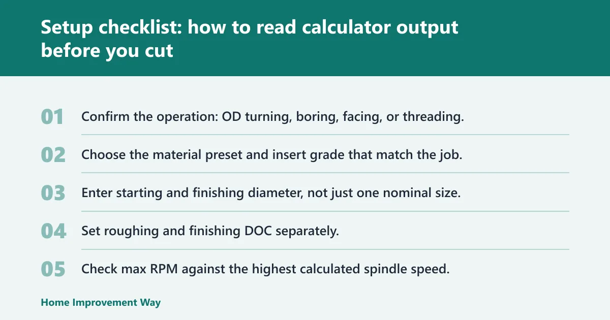
Use the calculator output as a pass/fail screen. If the numbers look acceptable but the setup is weak, the cut is still unsafe. The checklist below connects calculator inputs to shop decisions for OD turning, boring, and facing.
- Confirm the operation: OD turning, boring, facing, or threading.
- Choose the material preset and insert grade that match the job.
- Enter starting and finishing diameter, not just one nominal size.
- Set roughing and finishing DOC separately.
- Check max RPM against the highest calculated spindle speed.
- Compare estimated horsepower to usable machine power.
- Flag chatter risk if the part is long, thin-wall, or deeply bored.
- Lower speed or feed if interrupted cuts, poor clamping, or long overhang appear.
- Switch from constant surface speed to fixed RPM if the setup becomes unstable.
Chatter risk flags
Watch for slender workpieces, boring bars with too much stickout, small diameters with aggressive feed, and interrupted cuts from keyways or cross holes. Those conditions make calculator outputs optimistic. A conservative override is often the safer choice.
Thin-wall and small-diameter checks
Thin-wall parts need lighter DOC, lighter feed, and a harder look at rigidity. Small diameters can need high RPM, but high RPM alone does not make the cut safe. If the wall or bar flexes, the calculator is only part of the answer.
When to override the calculator
Override it when the insert geometry is mismatched, the cut is interrupted, the part sings at one speed, or the power estimate leaves little margin. The machine, holder, and workholding decide the final setting.
Frequently asked questions
What is a turning calculator used for?
A turning calculator can help estimate spindle speed, feed rate, material removal rate, cutting power, and torque for lathe work. In practice, it helps a machinist compare a proposed cut with machine limits, insert choice, part stiffness, and the risk of chatter before metal is removed.
How do you calculate spindle speed for turning?
Spindle speed comes from cutting speed and workpiece diameter. The calculator converts surface speed into RPM, so a larger diameter needs a lower RPM for the same cutting speed. Constant surface speed adjusts RPM as diameter changes; fixed RPM does not.
How do you calculate feed rate in lathe turning?
Feed rate in turning is feed per revolution multiplied by spindle speed. That gives linear feed speed in inches per minute or mm/min. The right value depends on roughing or finishing, insert geometry, and whether the setup can handle the chip load.
What is the difference between surface speed and RPM in turning?
Surface speed is the speed of the cutting edge past the workpiece surface, while RPM is spindle rotation speed. They are linked by diameter. As diameter changes, RPM must change to hold the same surface speed, which is why one fixed RPM is not ideal for every turning pass.
How do you calculate material removal rate for turning?
Material removal rate is based on depth of cut, feed, and cutting speed. It tells you how much volume the tool removes per minute. That number is useful for cycle time and productivity, but it also signals how much force and heat the setup may see.
How do you estimate cutting power for a turning operation?
Cutting power is estimated from the material removal load and the material’s specific cutting force kc. The calculator gives horsepower so you can compare the cut against machine capacity. If the number is close to the machine limit, reduce the cut or change the setup.
Sponsored / affiliate links. As an Amazon Associate I earn from qualifying purchases. I may earn additional commission from eligible campaigns.
 NatureTek Pest Control Kit - Pro Grade Plant Based Pest Control Spray, Long Lasting Effect, DIY Pesticide Sprayer, Bugs and Cockroach Repellent, Family/Petsafe Spray for Fly Mosquito
 Portable Tile Cutter Hand Tool with 1 Pair Pliers, 47.24 inch Cutting Length Manual Tile Cutters for DIY Enthusiasts, and Construction and Tile Industry Professionals